Add SPI support for RTEMS Raspberrypi4 BSP
Mainly refer to dev/bsps/shared/dev/spi/cadence-spi.c
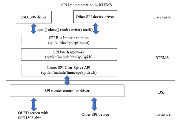
RTEMS uses a linux-based framework. The SPI Bus has been implemented in the RTEMS kernel. In this project, I need to implement the SPI master controller driver of RPi 4 and SSD1306 driver. The implementation of SPI in RTEMS as shown in the block diagram:
First, register the SPI host controller device on the bus. The register function is as follows:
rtems_status_code raspberrypi_spi_init(raspberrypi_spi_device device)
{
  raspberrypi_spi_bus *bus;
  int eno;
  volatile raspberrypi_spi *regs;
  const char *bus_path;

  bus = (raspberrypi_spi_bus *) spi_bus_alloc_and_init(sizeof(*bus));
  if (bus == NULL) {
    return RTEMS_UNSATISFIED;
  }

  switch (device) {
    case raspberrypi_SPI0:
      regs = (volatile raspberrypi_spi *) BCM2711_SPI0_BASE;
      bus_path = "/dev/spidev0";
      break;
    case raspberrypi_SPI3:
      regs = (volatile raspberrypi_spi *) BCM2711_SPI3_BASE;
      bus_path = "/dev/spidev3";
      break;
    case raspberrypi_SPI4:
      regs = (volatile raspberrypi_spi *) BCM2711_SPI4_BASE;
      bus_path = "/dev/spidev4";
      break;
    case raspberrypi_SPI5:
      regs = (volatile raspberrypi_spi *) BCM2711_SPI5_BASE;
      bus_path = "/dev/spidev5";
      break;
    case raspberrypi_SPI6:
      regs = (volatile raspberrypi_spi *) BCM2711_SPI6_BASE;
      bus_path = "/dev/spidev6";
      break;
    default:
      spi_bus_destroy_and_free(&bus->base);
      return RTEMS_INVALID_NUMBER;
      break;
  }

  eno = spi_bus_register(&bus->base, bus_path);
  if (eno != 0) {
    spi_bus_destroy_and_free(&bus->base);
    return RTEMS_UNSATISFIED;
  }

  eno = raspberrypi_spi_init_gpio(device);
  if (eno != 0) {
    spi_bus_destroy_and_free(&bus->base);
    return RTEMS_INVALID_NUMBER;
  }

  bus->regs = regs;
  bus->num_cs = 2;

  bus->base.transfer = raspberrypi_spi_transfer;
  bus->base.destroy = raspberrypi_spi_destroy;
  bus->base.setup = raspberrypi_spi_setup;
  bus->base.bits_per_word = 8;
  bus->base.max_speed_hz = 250000000;
  bus->base.cs = 0;
#ifdef BSP_SPI_USE_INTERRUPTS
  bus->irq = BCM2711_IRQ_SPI;

  eno = rtems_interrupt_handler_install(
    bus->irq,
    "SPI",
    RTEMS_INTERRUPT_SHARED,
    raspberrypi_spi_interrupt,
    bus
  );
  if (eno != RTEMS_SUCCESSFUL) {
    return EAGAIN;
  }
#endif

  return RTEMS_SUCCESSFUL;
}
Call spi_bus_alloc_and_init, which is a function implemented by the SPI bus driver and is located in the RTEMS kernel dev/cpukit/dev/spi/spi-bus.c.
Allocates a bus control from the heap and initializes it. After a sucessful allocation and initialization the bus control must be destroyed via spi_bus_destroy_and_free(). A registered bus control will be automatically destroyed in case the device file is unlinked. Make sure to call spi_bus_destroy_and_free() in a custom destruction handler.

parameter
size – The size of the bus control. This enables the addition of bus controller specific data to the base bus control. The bus control is zero initialized.

return
non-NULL The new bus control.
NULL An error occurred. The errno is set to indicate the error.
In the switch structure, select the SPI register address and the path name according to the value of the enum raspberrypi_spi_device. Register addresses are defined in the raspberrypi.h file.
Set various parameters and interface functions of the bus.
Use the macro definition BSP_SPI_USE_INTERRUPTS to select the driver to use interrupt mode or polling mode.
The installation of interrupt handlers, taking into account the situation of enabling multiple SPIs at the same time, use RTEMS_INTERRUPT_SHARED.
  eno = rtems_interrupt_handler_install(
    bus->irq,
    "SPI",
    RTEMS_INTERRUPT_SHARED,
    raspberrypi_spi_interrupt,
    bus
  );
Call spi_bus_register to register the device into the bus. This function is implemented in the SPI bus driver.
Call raspberrypi_spi_init_gpio to initialize gpio and set gpio to the correct function. The reason for placing this function after spi_bus_register: to avoid restoring gpio when spi_bus_register fails.
Next, I introduce the transfer function, which is used to handle SPI reading and writing.
static int raspberrypi_spi_transfer(
  spi_bus *base,
  const spi_ioc_transfer *msgs,
  uint32_t msg_count
)
{
  int rv = 0;
  raspberrypi_spi_bus *bus;
  bus = (raspberrypi_spi_bus *) base;

  rv = raspberrypi_spi_check_msg(bus, msgs, msg_count);
  if (rv == 0) {
    bus->msg_todo = msg_count;
    bus->msg = msgs;
#ifdef BSP_SPI_USE_INTERRUPTS
    bus->task_id = rtems_task_self();

    raspberrypi_spi_start(bus);
    rtems_event_transient_receive(RTEMS_WAIT, RTEMS_NO_TIMEOUT);
#else
    raspberrypi_spi_transfer_msg(bus);
#endif
  }

  return rv;
}
Call the raspberrypi_spi_check_msg function to check msg. It mainly checks whether a mode not supported by the driver is used and whether cs exceeds the total number of cs.
msg_count needs to be passed in here, because msgs is a queue with consecutive addresses and may contain multiple msg.
If the check passes, the part variables of the data information structure are assigned to the corresponding variables in the bus structure.
If you use interrupt mode, enter raspberrypi_spi_start, and use polling mode, enter raspberrypi_spi_transfer_msg.
This article mainly introduces the interrupt mode.
raspberrypi_spi_start only needs to start the transmission. For the RPI4 SPI controller, setting TA=1 will trigger the first interrupt immediately. I think this is the biggest difference from other BSPs.
static void raspberrypi_spi_start(raspberrypi_spi_bus *bus)
{
  volatile raspberrypi_spi *regs;
  regs = bus->regs;

  regs->spics = regs->spics | RPI_SPICS_INTR | RPI_SPICS_INTD;
  /*
   * Set TA = 1. This will immediately trigger a first interrupt with
   * DONE = 1.
   */
  regs->spics = regs->spics | RPI_SPICS_TA;
}
The interrupt handling function is as follows:
static void raspberrypi_spi_interrupt(void *arg)
{
  raspberrypi_spi_bus *bus;
  volatile raspberrypi_spi *regs;
  uint32_t val;

  bus = arg;
  regs = bus->regs;

  if (raspberrypi_spi_irq(regs)) {

    if (bus->todo > 0) {
      raspberrypi_spi_push(bus, regs);
    } else {
      --bus->msg_todo;
      ++bus->msg;
      raspberrypi_spi_next_msg(bus);
    }

    while (regs->spics & RPI_SPICS_RXD && bus->in_transfer > 0) {
      /*  RX FIFO contains at least 1 byte. */
      val = regs->spififo;
      if (bus->rx_buf != NULL) {
          *bus->rx_buf = (uint8_t)val;
          ++bus->rx_buf;
      }
      --bus->in_transfer;
    }

  }
}
The function raspberrypi_spi_irq is used to determine whether the interrupt is generated by the current SPI device. This allows multiple SPI devices to be used simultaneously.
The function raspberrypi_spi_next_msg is used to switch to the next msg and assign the remaining variables in the msg structure to the bus structure.
rtems_event_transient_receive and rtems_event_transient_send are crucial
rtems_event_transient_receive is called when the transfer starts.
	bus->task_id = rtems_task_self();
	rtems_event_transient_receive(RTEMS_WAIT, RTEMS_NO_TIMEOUT);
rtems_event_transient_send is called at the end of the transfer.
rtems_event_transient_send(bus->task_id);
It guarantees that a transfer command blocks until the end of the transfer.